|
4. Pinhole
 It is necessary to expand
a laser beam for the object or photoplate to be
exposed. It is better to use for this purpose 10-fold,
20-fold and 40-fold microscope objectives. The greater
fold of the objective (the less focal distance),
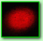
the greater expansion of the beam. However, if there
are some specks of dust on the lenses of the objective,
the laser beam diffracts and partly scatters. In
this case parasite interference pattern appears
in the form of contrast concentric rings, see photo.
This pattern disturbs homogeneity of the photoplate's
or object's exposure and quality of the recorded
hologram deteriorates. A pinhole is used to eliminate
this lack. It is a It is necessary to expand
a laser beam for the object or photoplate to be
exposed. It is better to use for this purpose 10-fold,
20-fold and 40-fold microscope objectives. The greater
fold of the objective (the less focal distance),
the greater expansion of the beam. However, if there
are some specks of dust on the lenses of the objective,
the laser beam diffracts and partly scatters. In
this case parasite interference pattern appears
in the form of contrast concentric rings, see photo.
This pattern disturbs homogeneity of the photoplate's
or object's exposure and quality of the recorded
hologram deteriorates. A pinhole is used to eliminate
this lack. It is a 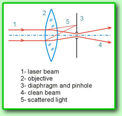 diaphragm with a small hole
located in the objective focal plane, see fig. Profile
of the laser beam is described by Gauss function,
it is not focused as a dot in the focus of the microscope
objective (this is idealization of geometric optics),
but it is shrunk up to a definite small size. Light
scattered on the specks of dust will spread at an
angle with an optical axis, so that it will be collected
at some distance from the axis in focal plane. The
size of hole is selected in such way the main laser
beam passes through the hole in the diaphragm and
light scattered on the specks is blocked. In that
case a clean homogeneous beam will come out of the
pinhole. Practice of the pinhole usage presents
the following approximate dependence of the diaphragm
hole size and the objective fold: diaphragm with a small hole
located in the objective focal plane, see fig. Profile
of the laser beam is described by Gauss function,
it is not focused as a dot in the focus of the microscope
objective (this is idealization of geometric optics),
but it is shrunk up to a definite small size. Light
scattered on the specks of dust will spread at an
angle with an optical axis, so that it will be collected
at some distance from the axis in focal plane. The
size of hole is selected in such way the main laser
beam passes through the hole in the diaphragm and
light scattered on the specks is blocked. In that
case a clean homogeneous beam will come out of the
pinhole. Practice of the pinhole usage presents
the following approximate dependence of the diaphragm
hole size and the objective fold:
- 30 micron is for 10-fold objective.
- 20 micron is for 20-fold objective.
- 15 micron is for 40-fold objective.
Quality of the objective and precision of the diaphragm
manufacture are very important for proper work of
the pinhole. 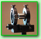 Presence of the objective
aberration and non-round form of the diaphragm hole
can dramatically worsen filtration of the laser
beam. It is better to produce the diaphragm hole
by means of lithography on the thin copper foil
and check quality of the hole using a microscope.
However, some virtuosos make a hole on the aluminium
chocolate foil with a sharp needle. To adjust a
pinhole precisely, the diaphragm should move along
the optical axis and two coordinates perpendicularly
to the optical axis by means of micrometer screws,
see photo. Presence of the objective
aberration and non-round form of the diaphragm hole
can dramatically worsen filtration of the laser
beam. It is better to produce the diaphragm hole
by means of lithography on the thin copper foil
and check quality of the hole using a microscope.
However, some virtuosos make a hole on the aluminium
chocolate foil with a sharp needle. To adjust a
pinhole precisely, the diaphragm should move along
the optical axis and two coordinates perpendicularly
to the optical axis by means of micrometer screws,
see photo.
Adjusting of the pinhole is executed in the following
way. Direct the laser beam to the centre of the
photoplate (or to the centre of the object). 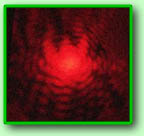 Press a glass plate to the
face of the microscope objective on the side of
the laser and fix it in such way that the laser
beam incidents on the centre of the input lens and
the beam reflected from the glass plate returns
back into the laser. (This operation is centering
of the objective along the optical axis.) Then move
the diaphragm along the optical axis and place it
near the objective's focal plane. If the diaphragm
moves very close to the focus you can see a "coarse
grain" reflection of the beam from the foil.
Reflected light has a very mobile granular structure.
Then take a piece of white paper, turn off the light
and move the diaphragm in the plane perpendicular
to the optical axis. Try to "catch" the
beam passed through the hole. The first time may
be not successful, you need some experience. Press a glass plate to the
face of the microscope objective on the side of
the laser and fix it in such way that the laser
beam incidents on the centre of the input lens and
the beam reflected from the glass plate returns
back into the laser. (This operation is centering
of the objective along the optical axis.) Then move
the diaphragm along the optical axis and place it
near the objective's focal plane. If the diaphragm
moves very close to the focus you can see a "coarse
grain" reflection of the beam from the foil.
Reflected light has a very mobile granular structure.
Then take a piece of white paper, turn off the light
and move the diaphragm in the plane perpendicular
to the optical axis. Try to "catch" the
beam passed through the hole. The first time may
be not successful, you need some experience. 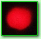 At the beginning of tuning,
the beam shape behind the pinhole will not be ideal
because the diaphragm is not in the objective focal
plane and the beam is cut with the hole edges, see
photo above. You should adjust the diaphragm position
thoroughly and obtain complete passing of the beam
through the hole. The beam will have round profile
without edge effects, see photo. At the beginning of tuning,
the beam shape behind the pinhole will not be ideal
because the diaphragm is not in the objective focal
plane and the beam is cut with the hole edges, see
photo above. You should adjust the diaphragm position
thoroughly and obtain complete passing of the beam
through the hole. The beam will have round profile
without edge effects, see photo.
References
R. J. Collier, K. B. Burckhardt, L. H. Lin "Optical
Holography", Academic Press, New York, 1971.
-->
|