|
24. Adjustment
of beams ratio and determination of hologram's
exposure time
Adjustment of the optimum ratio of intensities
of the reference and signal beams.
The next operation consists in adjustment
of the optimum ratio of intensities of the recording
beams. This fact reflects advantage of this
scheme in comparison with the Denisyuk scheme
in which variation of ratio of intensities of
the reference and signal beams can be achieved
only through changing brightness of the object
what isn’t always possible. Numerous experiments
of recording holograms with the help of the
copying scheme have led to some typical values
of the ratio between intensities of the reference
and signal beams. As a rule the ratio of 1:4
(the reference beam, R, is 4 times more powerful
than the signal beam, S, see fig.) is the most
universal value. In this case registration of
the
 interference
pattern on the hologram occurs on the one hand
practically linearly and on the other hand the
holographic image is sufficiently bright. This
fact is connected with particular features of
the light registration by the photographic emulsion.
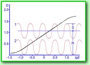
Typical characteristic curve of the photographic
emulsion – functional dependence of photometric
density on exposure is shown in the Fig.1 (black
line). The curve shows that by very weak (underexposure)
and very strong (over-exposure) exposures functional
dependence is nonlinear. The ratio of intensities
S:R as 1:4 just allows to locate the integral
distribution of illumination values caused by
the reference and signal beams on the linear
section of the characteristic curve, the sinusoid
1. By the ratio of the beam intensities higher
than 1:4 brightness of the hologram decreases
without visible improvement of quality. By the
ratio of the beams, S:R as 1:1 the image brightness
naturally increases but the amplitude of the
integral interference pattern drops down to
zero at the minima, the sinusoid 2, and because
of the nonlinear section of the characteristic
curve strong distortions by reproducing details
of the object, so called inter-modulation distortions.
It’s difficult to get rid of such unfavourable
ratio for the beams in the case of objects with
highly reflecting surfaces for example by recording
images of precious stones or either mirror or
well polished surfaces. Light reflects from
such objects, which fall on the photoplate develop
on the obtained hologram in the form of dark
spots, which deteriorate perception of the image
and are perceived as defects of the hologram.
They can be diminished through increasing the
ratio of the beam intensities up to 1:10 and
eve higher but then the total brightness of
the holographic image will decrease. In other
cases it’s possible to adjust optimum ratio
of intensities of the recording beams practically
for any object. For metallic objects or objects
covered by colours with metallic components
(for example aluminium paint) it’s possible
to bring the ratio of beams down to 1:3 and
for the light reflect even to 1:2 because metallic
surfaces don’t depolarize radiation and quality
of holograms remains high. For nonmetallic objects
depolarizing a reflected radiation it’s not
recommended to decrease the ratio in such a
way. For bright objects which have diffuse the
light (plaster figures, objects of white paper
or cardboard) it’s recommended to increase the
ratio of the beams up to 1:5 or even 1:6. If
there exists a possibility it’s better to record
a test reflection hologram and already on the
basis of it to draw a conclusion about the required
ratio of intensities of the recording beams. interference
pattern on the hologram occurs on the one hand
practically linearly and on the other hand the
holographic image is sufficiently bright. This
fact is connected with particular features of
the light registration by the photographic emulsion.
Typical characteristic curve of the photographic
emulsion – functional dependence of photometric
density on exposure is shown in the Fig.1 (black
line). The curve shows that by very weak (underexposure)
and very strong (over-exposure) exposures functional
dependence is nonlinear. The ratio of intensities
S:R as 1:4 just allows to locate the integral
distribution of illumination values caused by
the reference and signal beams on the linear
section of the characteristic curve, the sinusoid
1. By the ratio of the beam intensities higher
than 1:4 brightness of the hologram decreases
without visible improvement of quality. By the
ratio of the beams, S:R as 1:1 the image brightness
naturally increases but the amplitude of the
integral interference pattern drops down to
zero at the minima, the sinusoid 2, and because
of the nonlinear section of the characteristic
curve strong distortions by reproducing details
of the object, so called inter-modulation distortions.
It’s difficult to get rid of such unfavourable
ratio for the beams in the case of objects with
highly reflecting surfaces for example by recording
images of precious stones or either mirror or
well polished surfaces. Light reflects from
such objects, which fall on the photoplate develop
on the obtained hologram in the form of dark
spots, which deteriorate perception of the image
and are perceived as defects of the hologram.
They can be diminished through increasing the
ratio of the beam intensities up to 1:10 and
eve higher but then the total brightness of
the holographic image will decrease. In other
cases it’s possible to adjust optimum ratio
of intensities of the recording beams practically
for any object. For metallic objects or objects
covered by colours with metallic components
(for example aluminium paint) it’s possible
to bring the ratio of beams down to 1:3 and
for the light reflect even to 1:2 because metallic
surfaces don’t depolarize radiation and quality
of holograms remains high. For nonmetallic objects
depolarizing a reflected radiation it’s not
recommended to decrease the ratio in such a
way. For bright objects which have diffuse the
light (plaster figures, objects of white paper
or cardboard) it’s recommended to increase the
ratio of the beams up to 1:5 or even 1:6. If
there exists a possibility it’s better to record
a test reflection hologram and already on the
basis of it to draw a conclusion about the required
ratio of intensities of the recording beams.
Adjustment of the ratio of the beam intensities
is carried out by the beam splitter 2 (see
second fig. of Lesson 23). Special circular splitters
with dielectric sputtering of the reflecting
coating are manufactured and for these splitters
the reflection coefficient (and correspondingly
the transmission factor) changes smoothly depending
on the angle of rotation of the splitter. This
is the most accurate and convenient way of change
of the ratio of intensities of the recording
beams. With such a splitter no changes of the
trajectories of beams take place and no tuning
of the other scheme elements for example the
spatial filters which are the devices the most
sensitive to displacement of beams is needed.
In our arrangement change of the ratio of the
beams is based on the other well known principle
- dependence of the reflection factor of the
dielectric mirror on the incidence angle of
the beam. This is not a very convenient method
because by changing the inclination angle of
the mirror the trajectories of the reflected
and transmitted beams change together with variation
of the ratio of intensities of these beams and
a basic adjustment of the spatial filters should
be executed. Nevertheless the result of such
work consists in achievement of the optimum
ratio for the recording beams in the plane of
the hologram and correspondingly good quality
of the holographic image.
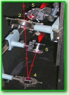 In
the fig. the fragment of separation of the beams
which includes the beam splitter 2 (numbers
correspond to second fig. of
Lesson 23), the turn
mirror 4 of the reference beam and the
spatial filters of the reference (lower) and
signal (upper) beams is shown. Measurement of
intensities of the beams is carried out with
the help of the photodiode in the plane of the
photoplate. On the one side of the photoplate
(or rather its equivalent – a piece of white
cardboard inserted into the frame) intensity
of the reference beam is measured and on the
other side – intensity of the signal beam is
measured. Measurements can be carried out in
relative units because only the ratio of intensities
of the reference and signal beams is important
for us but they also can be executed in absolute
units combining these measurements with the
following calculation of the time of exposure
of the hologram. It’s important to note that
measurements of intensity of the signal beam
are carried out in the brightest parts of it.
Since such parts can have very small dimensions
(for example glare), area of the photosensitive
surface of the photodiode shouldn’t be very
large. In our measurements the photodiode FD-7k
having the photosensitive surface with diameter
of 3 mm was used (see
Lesson 7). In
the fig. the fragment of separation of the beams
which includes the beam splitter 2 (numbers
correspond to second fig. of
Lesson 23), the turn
mirror 4 of the reference beam and the
spatial filters of the reference (lower) and
signal (upper) beams is shown. Measurement of
intensities of the beams is carried out with
the help of the photodiode in the plane of the
photoplate. On the one side of the photoplate
(or rather its equivalent – a piece of white
cardboard inserted into the frame) intensity
of the reference beam is measured and on the
other side – intensity of the signal beam is
measured. Measurements can be carried out in
relative units because only the ratio of intensities
of the reference and signal beams is important
for us but they also can be executed in absolute
units combining these measurements with the
following calculation of the time of exposure
of the hologram. It’s important to note that
measurements of intensity of the signal beam
are carried out in the brightest parts of it.
Since such parts can have very small dimensions
(for example glare), area of the photosensitive
surface of the photodiode shouldn’t be very
large. In our measurements the photodiode FD-7k
having the photosensitive surface with diameter
of 3 mm was used (see
Lesson 7).
Calculation of exposure time of the reflection
hologram.
For calculation of the hologram exposure
time illumination of the photographic plate
by the reference and signal beams is measured
as it was described in the
Lesson 7. By the ratio
of intensities 1:4 and higher illumination caused
by the signal beam can be neglected and the
exposure time is calculated only by the level
of illumination by the reference beam. But if
the ratio of illumination levels in the flashes
is 1:3 and less it’s necessary to take into
account influence of the signal beam and to
use total illumination by the reference and
signal beams by calculation of exposure otherwise
dark spots due to inter-modulation can again
appear on the hologram in these places because
of inaccuracy of calculations.
References
1. A.L.Kartushanskiy, L.V.Krasniy-Admoni. “Chemistry
and physics of photographic processes”, Moscow,
Chemistry, 1983. -->
|