|
16. Adjustment
of the optical system
Adjustment of the optical arrangement of the
pulse holographic setup can be conventionally
divided into two parts – tuning of the pulse
laser and adjustment of the illuminating light
beams.
Tuning of the pulse laser is executed if the
laser light beam energy has decreased or distribution
of intensity across the beam section has deteriorated.
Testing is executed in the following original
way. It’s known that if the ordinary photographic
paper or film is exposed by a very intensive
light beam reduction of the metallic silver
will take place without any development (photolysis).
This property of a photographic paper allows
very easily verifying quality of the laser beam
both inside the laser by its formation in the
infrared range and at the output from the laser.
A strip of photographic paper with a width of
3-4 cm is cut out and it is placed on the path
of the laser beam. When the beam hits a photographic
paper, a characteristic click is heard and a
dark spot - a trace of the beam appears by which
both the form of the beam section and approximately
its energy could be easily determined.
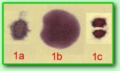 In
the fig.1(a, b) the photos of the beam in the
most important points – at the output from the
master oscillator and at the output from the
laser are shown, and at that the photographic
paper at the output from the laser was exposed
from the side of the substrate because of a
great energy of the output beam otherwise the
beam structure would be lost because of over-exposure.
In the fig. 1(c) the beam with a disturbed distribution
of intensity because of dustiness of the output
mirror of the master oscillator resonator is
shown. It's impossible to record a high-quality
hologram using such a beam and careful wiping
the appropriate laser element is needed. In
this case measurement of the laser beam energy
should be executed with the help of a special
instrument measuring the light pulse energy. In
the fig.1(a, b) the photos of the beam in the
most important points – at the output from the
master oscillator and at the output from the
laser are shown, and at that the photographic
paper at the output from the laser was exposed
from the side of the substrate because of a
great energy of the output beam otherwise the
beam structure would be lost because of over-exposure.
In the fig. 1(c) the beam with a disturbed distribution
of intensity because of dustiness of the output
mirror of the master oscillator resonator is
shown. It's impossible to record a high-quality
hologram using such a beam and careful wiping
the appropriate laser element is needed. In
this case measurement of the laser beam energy
should be executed with the help of a special
instrument measuring the light pulse energy.
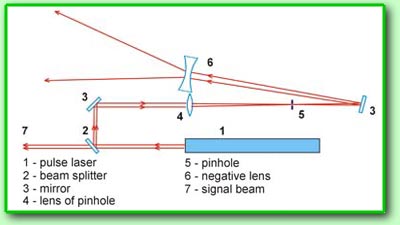 In
contrast to the Denisyuk scheme where only one
writing beam is used various variants of the
object illumination are possible in the pulse
setup. For a standard shooting e.g. portraits
or classic compositions it’s sufficient to form
three beams – one reference beam and two beams
illuminating the object. Scheme of formation
of the reference beam is shown in the fig. and
includes the following elements – the pulse
laser 1, the beam splitter 2,
the mirror 3, the spatial filter 4,
5 and the lens system 6 (the second
highly aperture lens is fixed on the shooting
cabin, and it can be seen in the third fig.
of the lesson 13)
for magnification of the beam sizes up to the
plate format. The beam splitter 2 represents
a plane-parallel glass plate. It means that
only several percent of the laser beam energy
are spent for formation of the reference beam. In
contrast to the Denisyuk scheme where only one
writing beam is used various variants of the
object illumination are possible in the pulse
setup. For a standard shooting e.g. portraits
or classic compositions it’s sufficient to form
three beams – one reference beam and two beams
illuminating the object. Scheme of formation
of the reference beam is shown in the fig. and
includes the following elements – the pulse
laser 1, the beam splitter 2,
the mirror 3, the spatial filter 4,
5 and the lens system 6 (the second
highly aperture lens is fixed on the shooting
cabin, and it can be seen in the third fig.
of the lesson 13)
for magnification of the beam sizes up to the
plate format. The beam splitter 2 represents
a plane-parallel glass plate. It means that
only several percent of the laser beam energy
are spent for formation of the reference beam.
 The
rest of energy is used for illumination of the
object. The spatial filter has an unusual structure
– the lens 4 has a focus of about one
meter. It’s connected with the fact that for
a short-focus length or for a microscope objective
the energy density of the beam in the focus
is so high that an electric disruption of the
air can occur. In this connection the laser
beam characteristics (spectrum, coherence) deteriorate
abruptly. Accordingly the diameter of aperture
of the diaphragm 5 of the spatial filter
is rather big – 1 mm. The
rest of energy is used for illumination of the
object. The spatial filter has an unusual structure
– the lens 4 has a focus of about one
meter. It’s connected with the fact that for
a short-focus length or for a microscope objective
the energy density of the beam in the focus
is so high that an electric disruption of the
air can occur. In this connection the laser
beam characteristics (spectrum, coherence) deteriorate
abruptly. Accordingly the diameter of aperture
of the diaphragm 5 of the spatial filter
is rather big – 1 mm.
 By
the same reason the first lens 6 of the
beam expander is negative and doesn’t focus
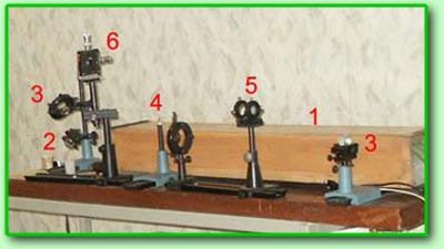
the laser beam at all. Adjustment of the reference
beam is reduced to testing operation of the
spatial filter and position of the reference
beam on the photoplate. The beam should pass
through the diaphragm orifice exactly in the
centre not touching the edges and should uniformly
illuminate the photoplate plane. Scheme of formation
of the reference beam is located on the same
table where the pulse laser is situated, see
photo above. By
the same reason the first lens 6 of the
beam expander is negative and doesn’t focus
the laser beam at all. Adjustment of the reference
beam is reduced to testing operation of the
spatial filter and position of the reference
beam on the photoplate. The beam should pass
through the diaphragm orifice exactly in the
centre not touching the edges and should uniformly
illuminate the photoplate plane. Scheme of formation
of the reference beam is located on the same
table where the pulse laser is situated, see
photo above.
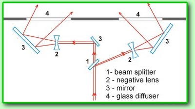
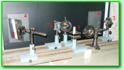 Scheme
of formation of the beams illuminating the object
is shown in the fig. above. The splitter
1 divides the beam in two beams of approximately
equal intensity, which are expanded by the negative
lenses 2 and mirrors 3 and directed
to the glass diffusers 4. The light diffused
by the diffusers illuminates the object being
shot from two sides. Scheme of formation of
the beams illuminating the object is located
on the special table on the front wall of the
shooting cabin, see photo.
--> Scheme
of formation of the beams illuminating the object
is shown in the fig. above. The splitter
1 divides the beam in two beams of approximately
equal intensity, which are expanded by the negative
lenses 2 and mirrors 3 and directed
to the glass diffusers 4. The light diffused
by the diffusers illuminates the object being
shot from two sides. Scheme of formation of
the beams illuminating the object is located
on the special table on the front wall of the
shooting cabin, see photo.
-->
|