|
22. Scheme
of transmission hologram copying
So we came to the last step of making the pulse
hologram – copying a three-dimensional image
from the transmission master-hologram to the
reflection hologram. Copying solves two important
problems: First of all the reflection hologram
restores the adequate three-dimensional image
visible in normal white light. Secondly, position
of the image can be changed with respect to
photoplate. As a rule a part of the image is
moved forward before the photoplate what leads
to increase of the effect of image reality.
You can “touch” the outstanding part of the
object for example a nose of a dog.
For usual observation of the image restored
by the transmission hologram it’s sufficient
to illuminate it by a laser beam from the side
from which the recording reference beam had
been falling (see the second fig. in the
Lesson 13). At that
the transmission hologram restores a virtual,
pseudoscopic image. So a full illusion
of presence of the object behind the hologram
is created. But if the transmission hologram
is illuminated by a laser beam from the opposite
side the real, so-called
orthoscopic image located before
the hologram is restored. This image is called
a real image because it's really formed in the
space before the hologram and it can be seen
on the white screen set in the image plane.
Properties of the orthoscopic image are quite
unusual - it is as if turned inside out (look
at the Denisyuk hologram from the side of emulsion
layer and You’ll see the real, orthoscopic image).
But namely such way of illumination of the transmission
hologram allows copying the restored three-dimensional
image with its transfer to the plane of the
photoplate and even before the photoplate.
The scheme of copying of the reflection hologram
is shown on the fig. below. In order to better
understand the peculiarities of copying process
the scheme is shown in such a way that positions
of the transmission hologram and the restored
image correspond to positions of the photoplate
and the object by recording the transmission
hologram (see the first fig. of
Lesson 13). Position
of the observer’s eyes is also shown in the
figure and this position is the same both for
observation of the virtual image restored by
the transmission hologram (by the opposite direction
of the reconstruction beam!) and for the final
image restored by the reflection hologram got
through exposure and chemical treatment of the
photoplate.
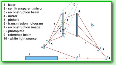 The
laser beam 1 is divided in two beams
by the semitransparent mirror 2. The
reconstruction beam 3 is directed by
the mirror 4 to the spatial filter
5. The enlarged and cleared beam falls on
the transmission hologram 6 from the
side of the glass substrate and restores the
real, orthoscopic image 7, located in
the same place as the object during recording
the transmission hologram. In the region of
the reconstruction of real image the photoplate
8 is set. Adjusting the distance between
the transmission hologram and the photoplate
it's possible to change position of the reconstruction
image by placing it on the plane of the reflection
hologram and even before it! The reference beam
9 is directed to the spatial filter
5 by the mirror 4 and falls on
the photoplate under the Brewster’s angle. Since
the object and reference beams are fall on the
photoplate from different sides the reflection
hologram is registered on it and this hologram
can restore a three-dimensional image in the
usual white light. Direction of incidence of
the reference beam is due to be specified more
exactly. As the image restored by the reflection
hologram is orthoscopic the reference beam shall
have the direction opposite to the direction
of the beam which will illuminate the obtained
reflection hologram. Direction of illumination
from the reconstructing light source 10
is shown on the figure by dotted lines. For
this reason the photoplate is turned to the
reference beam by its emulsion side. The examined
scheme of copying the reflection hologram demonstrates
unusual possibilities of manipulating three-dimensional
images in the coherent optical systems with
diffraction elements.
--> The
laser beam 1 is divided in two beams
by the semitransparent mirror 2. The
reconstruction beam 3 is directed by
the mirror 4 to the spatial filter
5. The enlarged and cleared beam falls on
the transmission hologram 6 from the
side of the glass substrate and restores the
real, orthoscopic image 7, located in
the same place as the object during recording
the transmission hologram. In the region of
the reconstruction of real image the photoplate
8 is set. Adjusting the distance between
the transmission hologram and the photoplate
it's possible to change position of the reconstruction
image by placing it on the plane of the reflection
hologram and even before it! The reference beam
9 is directed to the spatial filter
5 by the mirror 4 and falls on
the photoplate under the Brewster’s angle. Since
the object and reference beams are fall on the
photoplate from different sides the reflection
hologram is registered on it and this hologram
can restore a three-dimensional image in the
usual white light. Direction of incidence of
the reference beam is due to be specified more
exactly. As the image restored by the reflection
hologram is orthoscopic the reference beam shall
have the direction opposite to the direction
of the beam which will illuminate the obtained
reflection hologram. Direction of illumination
from the reconstructing light source 10
is shown on the figure by dotted lines. For
this reason the photoplate is turned to the
reference beam by its emulsion side. The examined
scheme of copying the reflection hologram demonstrates
unusual possibilities of manipulating three-dimensional
images in the coherent optical systems with
diffraction elements.
-->
|